
|
|
 |
DESCRIPTION
The NOISE
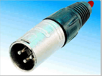
PLUG is a complete precision pink noise generator built in a XLR microphone
connector. Inside the NOISE PLUG is an ultra wideband, avalanche junction
white noise source. The output of the white noise source is frequency limited,
amplified and passed through a precision -3db per octave low pass filter.
The result is a full audio spectrum noise source with equal energy distribution
in all octaves.
MANY USES
The NOISE
PLUG can be used to check over all audio system operation, adjust speaker
crossover points and balance, check frequency response of amplifiers, tape
decks and other audio components, and adjust system equalization. Pink
noise is also often used in noise masking systems to reduce annoyance from
other noise sources such as heavy machinery and air handling systems.
EASY TO USE
The NOISE
PLUG is extremely easy to use. Simply plug it into a phantom powered microphone
input on your mixer and turn up the volume. A bright red LED indicator
on the back of the NOISE PLUG shows that phantom power is present and that
the NOISE PLUG is operating. Because it's phantom powered, there are no
batteries to go dead or bulky plug-in power supplies to deal with. It's
always ready for immediate use.
NOISE PLUG INSTRUCTIONS
1 - GENERAL DESCRIPTION
The NOISE PLUG is a complete precision pink noise generator built in a XLR microphone connector. Inside the NOISE PLUG is an ultra wideband, avalanche junction white noise source. The output of the white noise source is frequency limited, amplified and passed through a precision -3db per octave low pass filter. The result is a full audio spectrum noise source with equal energy distribution in all octaves.
The
NOISE PLUG can be used to check over all audio system operation, adjust
speaker crossover points and balance, check frequency response of amplifiers,
tape decks and other audio components, and adjust system equalization.
Pink noise is also often used in noise masking systems to reduce annoyance
from other noise sources such as heavy machinery and air handling systems.
2 - SET UP
To use the NOISE PLUG, first choose an unused microphone input on your mixer. Make sure that the fader for the selected input is all the way down and all EQ settings are centered (flat). Set the input trim or gain to 40db or about the same as you would use for a dynamic microphone. If the input has a phantom power switch, turn it on. Now insert the NOISE PLUG into the connector for the selected channel. It won't hurt the NOISE PLUG to connect and disconnect it while phantom power is on, just make certain that the fader for that channel is down to prevent any loud pops.
As
soon as NOISE PLUG is connected, the LED on the back should light up. If
it doesn't light, phantom power is not being provided by the mixer. Check
to see if there is a master phantom power switch and turn it on. Once the
LED is illuminated, slowly bring up the fader. You will hear a the pink
noise test signal.
3 - WHAT IS PINK NOISE?
Pink noise
is an audio test signal that contains all the frequencies in the audio
spectrum with equal energy in each octave. Unlike white noise, which contains
equal energy at all frequencies, pink noise contains less energy in the
higher audio frequencies than in the lower ones. This is because the higher
octaves have wider frequency content than the lower ones. For example,
if your were to slice the audio spectrum into one hertz "slices", the octave
between 100Hz and 200Hz would contain 100 such slices. The octave, between
1KHz and 2KHz would contain 1000 slices, while the octave between 10KHz
and 20KHz would contain 10,000 slices. It can be seen that if each slice
contained the same energy, there would be much more overall energy in the
higher octaves than in the lower ones. This is the case with white noise.
White noise can be converted to pink noise by passing it through a low
pass filter with a -3db per octave roll off.
4 - USING PINK NOISE
Pink noise is usually used in conjunction with an audio spectrum analyzer, sometimes referred to as a real time analyzer or RTA for short. Pink noise is sent to the device under test, be it a single component or complete sound system. The output of the device or system is then viewed on the RTA. The RTA will show the relative amplitudes, measured in db, of each one-third octave interval over the entire audio spectrum. Unless the device under test is an equalizer, cross-over or other frequency limiting device, the display on the RTA is usually expected to be a straight line.
Although not as scientific or precise, many experienced sound engineers can EQ an entire sound system, to within a few db of "flat", using only their ears while listening to pink noise.